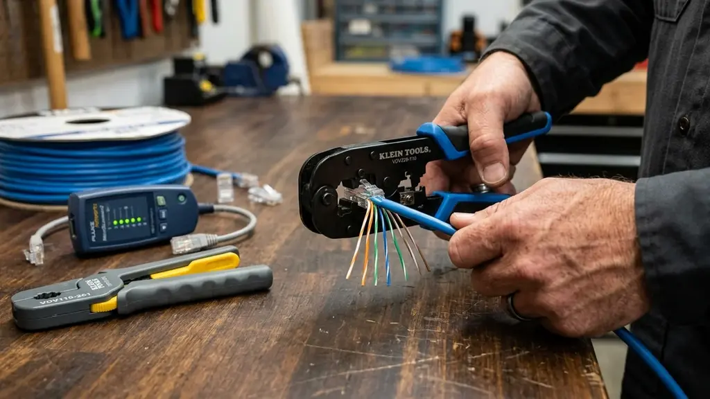
Master custom-length Ethernet cable creation. Complete beginner guide to terminating Cat6 cables using pass-through connectors and T568B pinout.
Learning how to terminate your own custom-length Ethernet cables is one of the most rewarding and cost-effective skills in DIY home networking. Whether you need an exact 4.5-foot patch cable for a clean desk setup or a 75-foot run through an attic, creating your own cables eliminates messy slack coils and saves money. Follow our step-by-step masterclass using modern Pass-Through RJ45 connectors and the universal T568B color standard.
Essential Toolkit Checklist
- Pass-Through RJ45 Crimper: (e.g. Klein Tools or SGILE crimper with integrated flush trimmer).
- Cat6 Pass-Through RJ45 Plugs + Strain Boots: 50-micron gold 3-prong connectors.
- Cat6 Cable Stripper & Snips: For scoring the outer PVC jacket without nicking copper wires.
- RJ45 Continuity Cable Tester: To verify pinout continuity from Pin 1 to Pin 8.
The Universal T568B Wiring Pinout Diagram
If your ISP delivers high speeds but your connection drops or suffers from bufferbloat during multi-device use, upgrading these verified components eliminates the bottleneck:
Pin 1: White / Orange
Pin 2: Orange
Pin 3: White / Green
Pin 4: Blue
Pin 5: White / Blue
Pin 6: Green
Pin 7: White / Brown
Pin 8: Brown
Step-by-Step Crimping Walkthrough
- Step 1 (Slide Boot): Slide the rubber strain relief boot onto the cable first.
- Step 2 (Strip Jacket): Strip 1.5 inches of outer cable jacket and cut away the internal plastic cross-spline.
- Step 3 (Untwist & Align): Untwist the pairs and align them in exact T568B sequence. Flatten the wires firmly between your fingers.
- Step 4 (Insert Through Plug): Push the aligned wires through the pass-through plug until the outer jacket enters the rear strain relief cavity.
- Step 5 (Visually Inspect): Double-check the color sequence through the clear plastic front of the plug.
- Step 6 (Crimp & Trim): Insert into the crimper and squeeze firmly. The tool will crimp the gold pins into the wires and shear off excess copper flush.
- Step 7 (Test): Plug both ends into your RJ45 cable tester. Pins 1 through 8 must light up sequentially green!
T568A vs T568B: What Is the Difference?
Both T568A and T568B wire color pinouts are electrically identical and deliver the exact same gigabit throughput. The only difference is the swapping of the Green and Orange wire pairs (Pins 1/2 and Pins 3/6):
- T568B (Standard): The universal standard for 99% of residential and commercial network installations in the United States.
- T568A (Government / Legacy): Used primarily in older US federal government installations and residential voice wiring.
- Straight-Through Cable: Terminating both ends in T568B creates a standard straight-through cable for connecting PCs to routers and switches.
Troubleshooting Crimping Errors
Experiencing packet loss, jitter spikes, or evening ISP throttling? Connect directly to dedicated gaming routes or bypass traffic shaping:
- Issue: Cable Tester Shows Flashing Pin 1 & 2 Out of Order: You crossed White/Orange and Orange. Cut off the plug and re-crimp with careful color alignment.
- Issue: Speed Capped at 100 Mbps: Gigabit Ethernet requires all 8 wires; if Pins 4, 5, 7, or 8 have poor contact, link speed drops to 100M. Re-crimp with a firm squeeze.
Why Maintaining Internal Pair Twist Is Essential for Cat6
When terminating high-performance Cat6 cables, never untwist the wire pairs more than 1/2 inch (12.7 mm) from the physical termination point. The physical twist pitch of the wire pairs is what creates the electromagnetic cancellation that suppresses Near-End Crosstalk (NEXT).
Pass-Through RJ45 connectors allow you to push the outer cable jacket deep into the plug body, keeping untwisted wire lengths under 1/8 inch for maximum 10-Gigabit signal integrity.
Step-by-Step Summary for Perfect Crimps
- Always remember the T568B rhyme: Orange-White, Orange, Green-White, Blue, Blue-White, Green, Brown-White, Brown.
- Use pass-through connectors for instant visual alignment.
- Test every completed cable with an RJ45 continuity meter before deployment.
Keystone Jack Termination vs Modular RJ45 Crimping
When running in-wall Ethernet cables from room to room, always terminate the wall ends into Cat6 RJ45 Keystone Jacks mounted inside wall faceplates using a punch-down tool, and use flexible stranded patch cables to connect from the wall plate to your PC.
Cable Stripper Depth Adjustment & Conductor Scoring
When using an adjustable cable stripper, set the blade depth so it scores only the outer PVC jacket without touching the copper wire insulation beneath. Nicking the internal wire insulation can cause microscopic copper fatigue that leads to intermittent link drops.
RJ45 Modular Plug Locking Tab Cycle Life
High-grade polycarbonate pass-through RJ45 plugs feature flexible, high-tensile locking tabs tested for over 1,000 insertion and removal cycles without snapping or losing retention force inside switch ports.
Signal Integrity, NEXT Crosstalk & TIA-568 Certification for How to Crimp an RJ45 Cat6 Ethernet Cable (Step-by-Step with T568B Diagram)
In physical-layer deployments involving How to Crimp an RJ45 Cat6 Ethernet Cable (Step-by-Step with T568B Diagram), high-frequency packet loss rarely stems from raw copper breakages; instead, it is triggered by Near-End Crosstalk (NEXT), return loss reflections, and untwisted pair terminations exceeding the 13 mm (0.5 inch) ANSI/TIA-568.2-D specification. When operating at 2.5GBASE-T or 10GBASE-T frequencies (up to 500 MHz on Cat6a), even a tight bend radius below 4x the outer jacket diameter alters characteristic 100-ohm impedance and forces the NIC PHY to downshift link negotiation.
For installations integrating how to crimp rj45 cat6 cable, t568b color code diagram, diy ethernet cable termination guide, rj45 crimping tool tutorial, always separate unshielded twisted pair (UTP) runs from parallel 120V/240V AC Romex power lines by at least 15 cm (6 inches), crossing high-voltage conduits exclusively at 90-degree angles. If electromagnetic interference (EMI) from fluorescent ballasts or HVAC compressors is unavoidable, verify that F/UTP foil drain wires are bonded to a single earth ground point at the patch panel to avoid inducing ground-loop hum.
| Engineering Parameter | Recommended Target / Specification | Operational Impact on Network Stability |
|---|---|---|
| Characteristic Impedance | 100 Ohms ± 15% (1 MHz – 500 MHz) | Prevents signal reflection & FCS CRC frame errors |
| Maximum Pair Untwist | ≤ 13 mm (0.5 in) at Keystone / RJ45 Pin | Preserves NEXT crosstalk margin on 10Gbps links |
| Minimum Bend Radius | 4× Cable Outer Diameter (Static) | Prevents internal conductor micro-fractures & attenuation |
| Conductor Metallurgy | 100% Pure Bare Solid Annealed Copper (23 AWG) | Eliminates PoE++ voltage drop & thermal rise vs CCA |
Field Deployment & Verification Checklist
Before finalizing your setup for How to Crimp an RJ45 Cat6 Ethernet Cable (Step-by-Step with T568B Diagram), run a baseline diagnostic before and after applying hardware or firmware changes. Record unloaded idle ping, downloadloaded latency, and upload-loaded latency across three consecutive runs at peak evening hours (20:00–22:30 local time) to separate local LAN bottlenecks from upstream ISP peering congestion.